

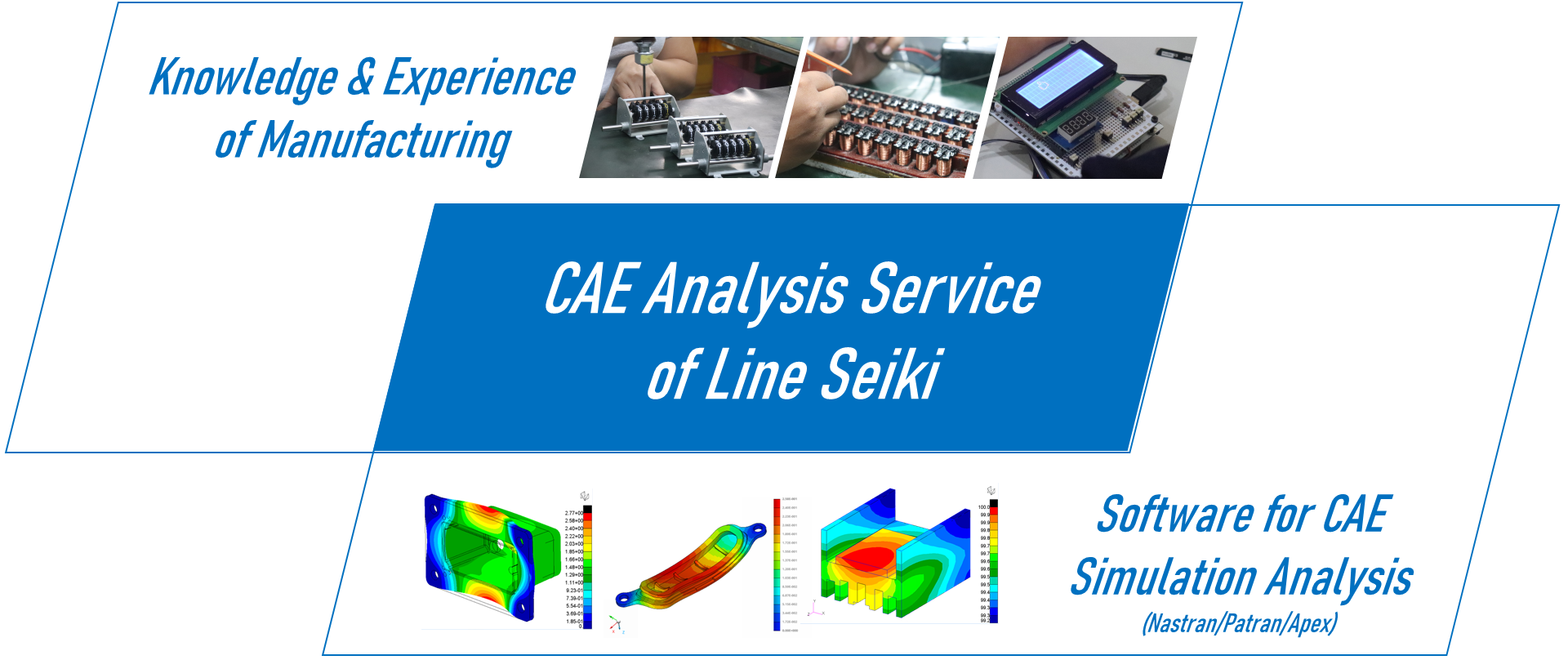
Simulation Analysis Service of Line Seiki
Line Seiki is a manufacturer: We design, produce and inspect our products in our own factory. Though we have a long-term experience as a manufacturer, our newly introduced CAE analysis has shortened the lead time, and reduced the cost of our design & development phase. In addition, we witnessed efficient improvements at our production lines.
We can be entrusted with the simulation analysis which utilizes Finite Element Method.
Just count on Line Seiki. We can perform analyses on a range of products: an intricate mechanical product which consists of both plastic and metal parts, a product which has an electronic circuit of PCB, etc. We will conduct CAE simulation services which can only be done by Line Seiki whose expertise and experience of manufacturing has been cultivated over 70+ years since its establishment.
If you are encountering any issues like the ones below, get in touch with us today. We will make an offer based on your circumstances and requests.
- You want to shorten the time required for design & development and/or prototype evaluation.
It is necessary to reduce the prototype quantities and reduce the cost of design/development.
You need to make the entire design process more efficient.
It is difficult/impossible to replicate the actual usage environment.
There is a spot/area where temperature is hard to measure.
- In design phase, we need to confirm sufficient durability.
- You want to check beforehand the possibility that the product defects/fails.
- You need to design our products with safety and user-friendliness.
- It is necessary to provide a “safety margin” against fatigue failure.
- There is a need to reduce the number of revisions/modifications of products due to their insufficient strength.
- You want to pursue an optimal structure to prevent sudden failure of (a part of) product.
- I want to prevent problems that occur from manufacturing processes after starting the mass production.
- I want to take proactive measures to mitigate the risk and ensure integrity.
- It is necessary to take measures to prevent the structure from failing.
Types of Simulation Analysis
Through the analysis of Structural/Static Simulation, you are able to evaluate strength of a designed structure, and to predict the possibility of its failure.
― Advantages ―
・It enables you to verify the safety and the durability of the designed structure.
・It can virtually replicate an environment in which a product under development is to be used.
― How to Conduct the Simulation ―
・The stress on each element that occurs when a load is applied to the designed structure will be calculated and quantified.
・The maximum value of stress that occurs in the structure under applied loads and its location(s) will be determined. The maximum deformation of the structure will also be quantified and can be visualized.
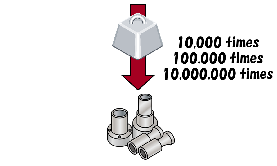
The analysis of Fatigue Simulation will enable you to design a product considering fatigue failure.
― Advantages ―
・It enables the verification of whether the durability of a designed structure is adequate.
・It is possible to determine the areas where earlier fatigue failure could occur.
― How to Conduct the Simulation ―
・Fatigue life is quantified.
・”Cycles of usage until the structure fails” are visualized.
・The maximum deformation the structure will experience under applied loads is quantified and visualized.
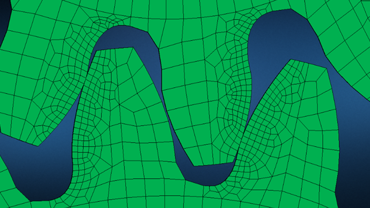
Through the analysis of Vibration & Dynamics Simulation, it is possible to determine the behavior of a designed structure in response to various vibrations, helping in the prevention of structural failure.
― Advantages ―
・It allows the verification of the possibility of unexpected excessive vibrations from development phase.
・It is useful for optimizing structural performance, and ensuring structural integrity under dynamic loads.
・It will enable you to determine what should be modified in the design to avoid resonance point.
― How to Conduct the Simulation ―
・Modal Analysis: It focuses on understanding natural frequency and vibration patterns (called mode shapes) of structures.
・Frequency Response Analysis: It helps us understand how the system’s output changes in relation to the frequency of the input dynamic load.
・Transient Response Analysis: It is a study of how a structure or system responds to time-varying loads or sudden changes in operating conditions.
In addition, Line Seiki can provide the following analyses:
Thermal Simulation, Buckling Simulation, Contact Analysis, Explicit Dynamics Simulation, Implicit Mechanics Simulation, Manufacturing Processes Simulation, Computational Fluid Dynamics Simulation, Multibody Dynamics Simulation, Additive Manufacturing Simulation, Multi-scale Material Modeling, Topology Optimization, Acoustic Simulation, Drop Simulation
Simulation Software 
- Pre-Processing: MSC Apex/Patran ―― Create a mesh model / define boundary conditions (material properties, constraint, etc.)
- Solver: MSC Nastran (Multidisciplinary Structural Analysis)
- Post-Processing: MSC Apex/Patran ―― Process the results of computation for visual perception, using 3D data and mapping
- Analysis Capabilities: Linear and non-linear Finite Element Analysis (FEA)
How We Provide the Services
Basic Flow
(1) Interview:
We conduct an interview in person or through web conference app to see your requirements/issues.
(2) Offer:
Based on the interview, we propose simulation analysis. (Types of analysis can be reviewed.)
(3) Trial:
Part of simulation analysis can be tried in advance. Trial fee is on a case-by-case basis. We kindly ask you to share CAD model (design data) with us before conducting the trial simulation analysis.
(4) Report:
We will submit the trial results to you.
(5) Simulation Analysis & Report:
Based on the proposal of simulation analysis, we will carry out CAE simulation analysis and submit the report of analysis results.
Should you have any questions/concern to consider CAE simulation analysis, please feel free to contact us anytime before the provision of services.
(Ex.) “It is difficult to share CAD model.” “It is necessary to conclude NDA (Non-Disclosure Agreement).” etc.
If you need any analysis, please do not hesitate to contact us.
Traditional vs Simulation-Driven method
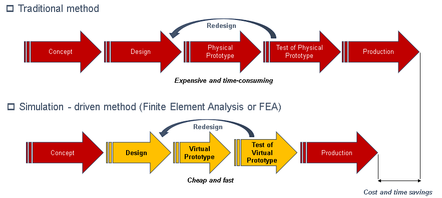
□ Simulation-Driven Method (FEA) : Easy, fast and cost-efficient design cycles
Reference: forcetechnology.com
Case studies
The images below show a comparison between simulated and actual test results.
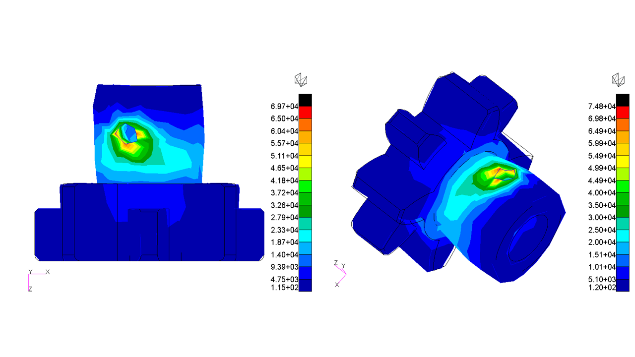
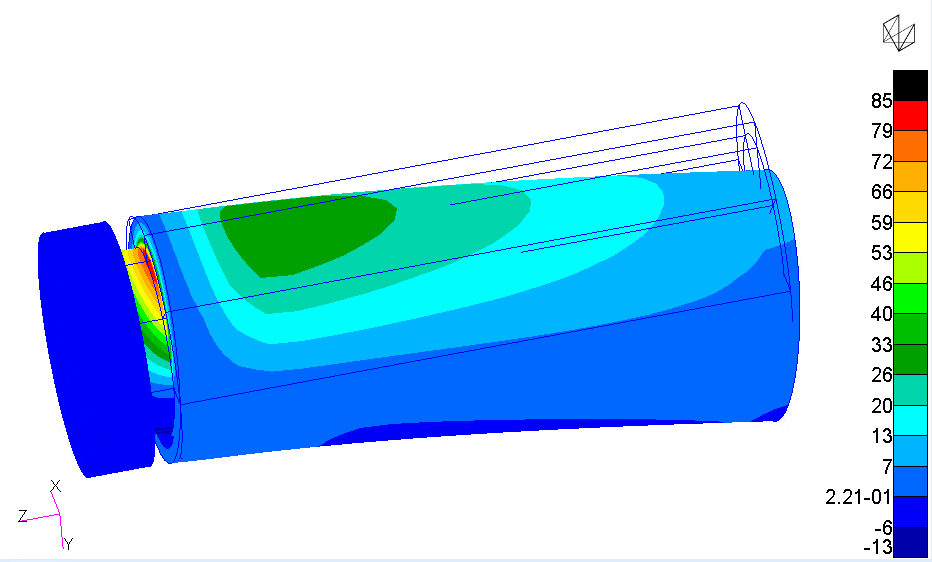
□ Pinion failure analysis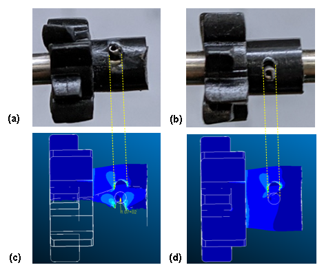
(a) actual – sample #1 (b) actual – sample #2 (c) sectioned FEA result (d) top view FEA result.
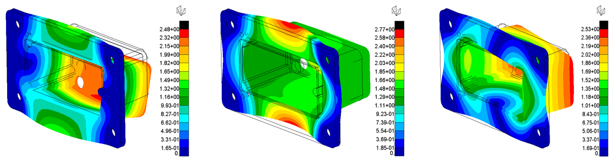
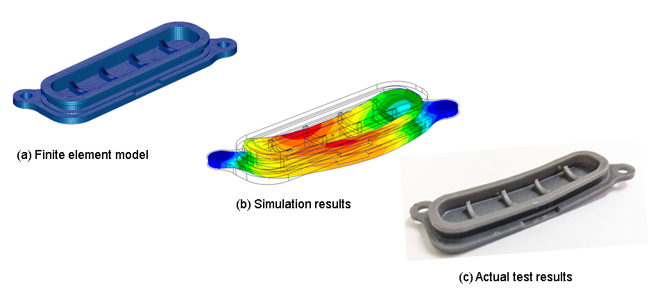
□ Screw Boss Failure Analysis
Failure that was found in a prototype in the testing phase
Can’t we clarify issues which lurk in design itself preliminary?
>>> Yes, we can review the design beforehand by introducing CAE simulation analysis in the design phase!
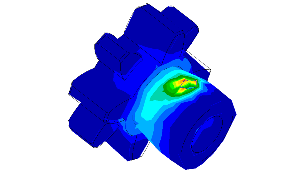
By using design data (3D model)…,
…stress distribution is shown by Finite Element Analysis through the software of CAE simulation analysis.
This picture was generated by post-processing to show theoretical stress distribution. Higher stress occurs in red locations, which shows higher risk of failure is assumed around the locations.
These pictures show analysis results correlate with the actual failure.
□ Cover thermal buckling analysis
-Related Page-
Get in Touch with Us
If you have any questions and/or requests concerning our CAE (Computer-Aided Engineering) analysis service, get in touch with us by clicking here.